JonHylands
New member
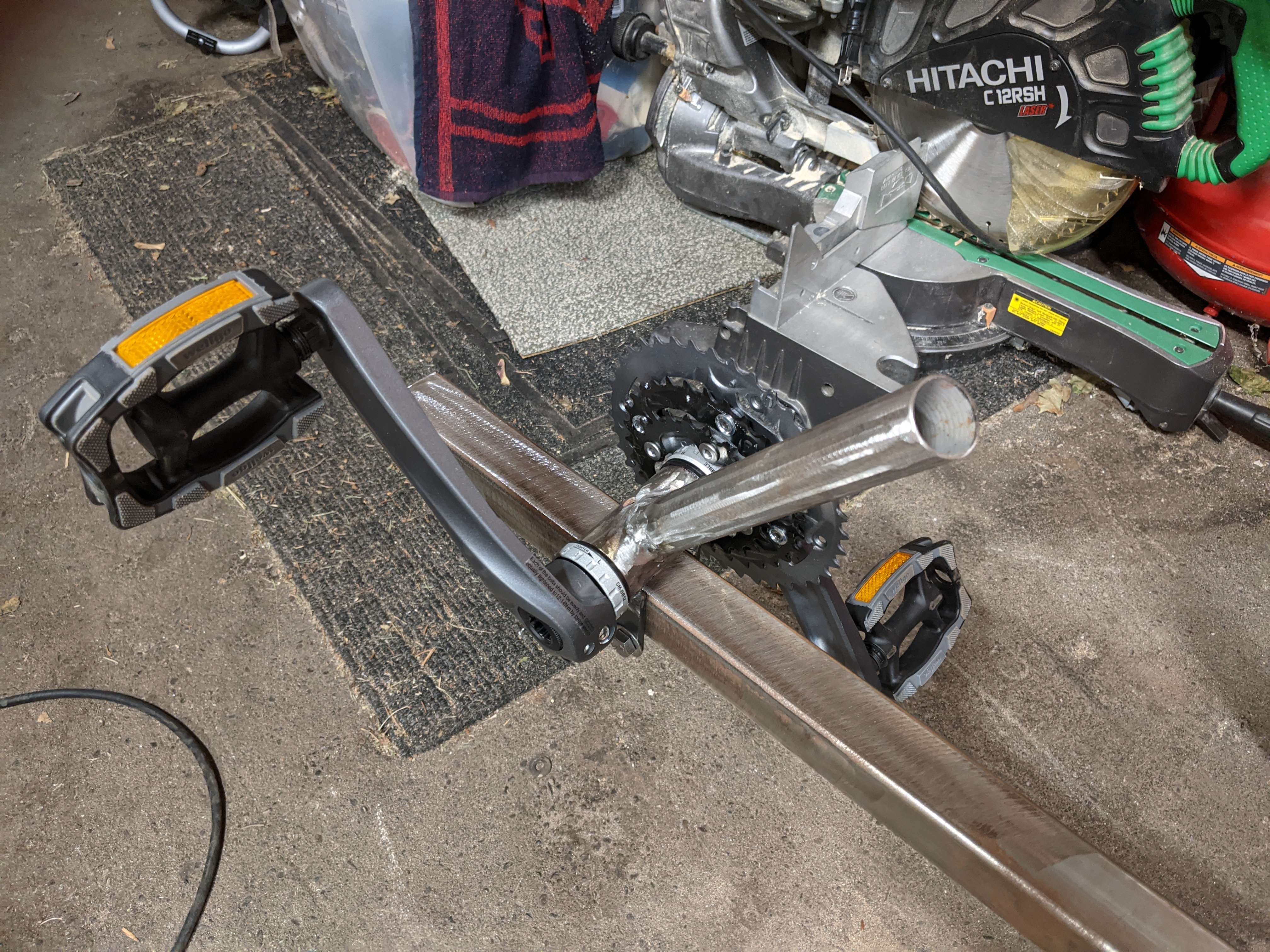
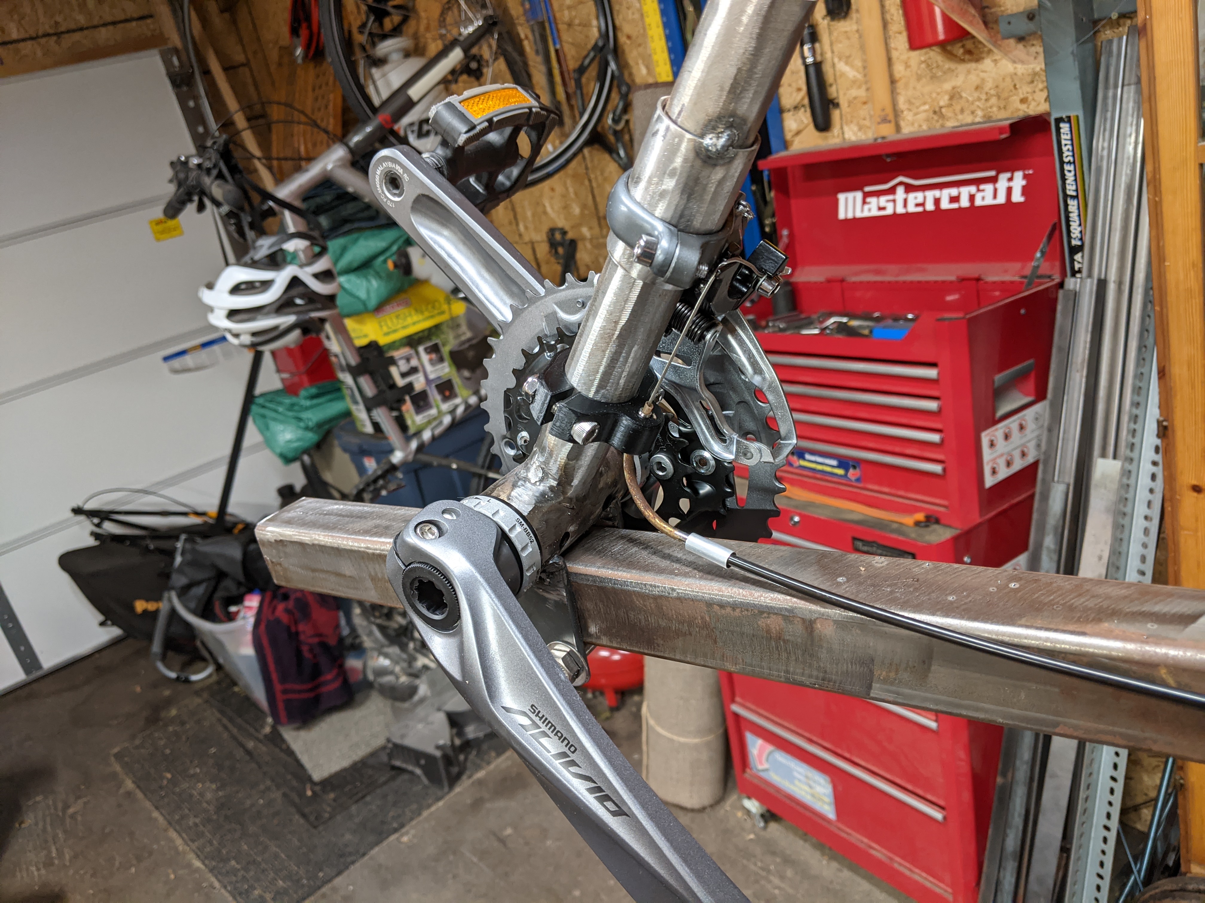
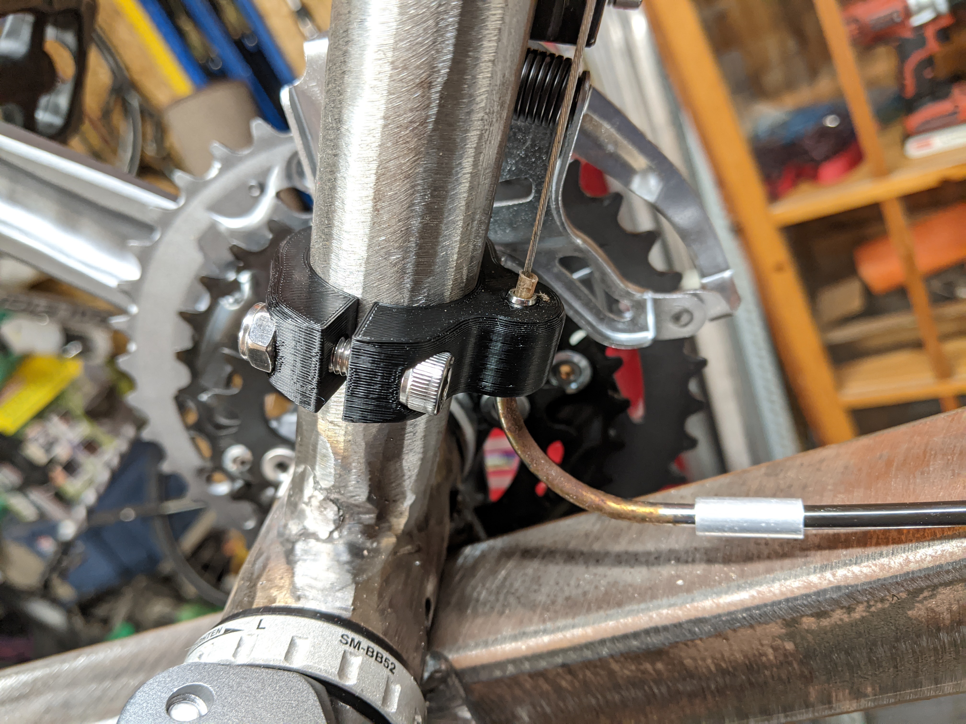
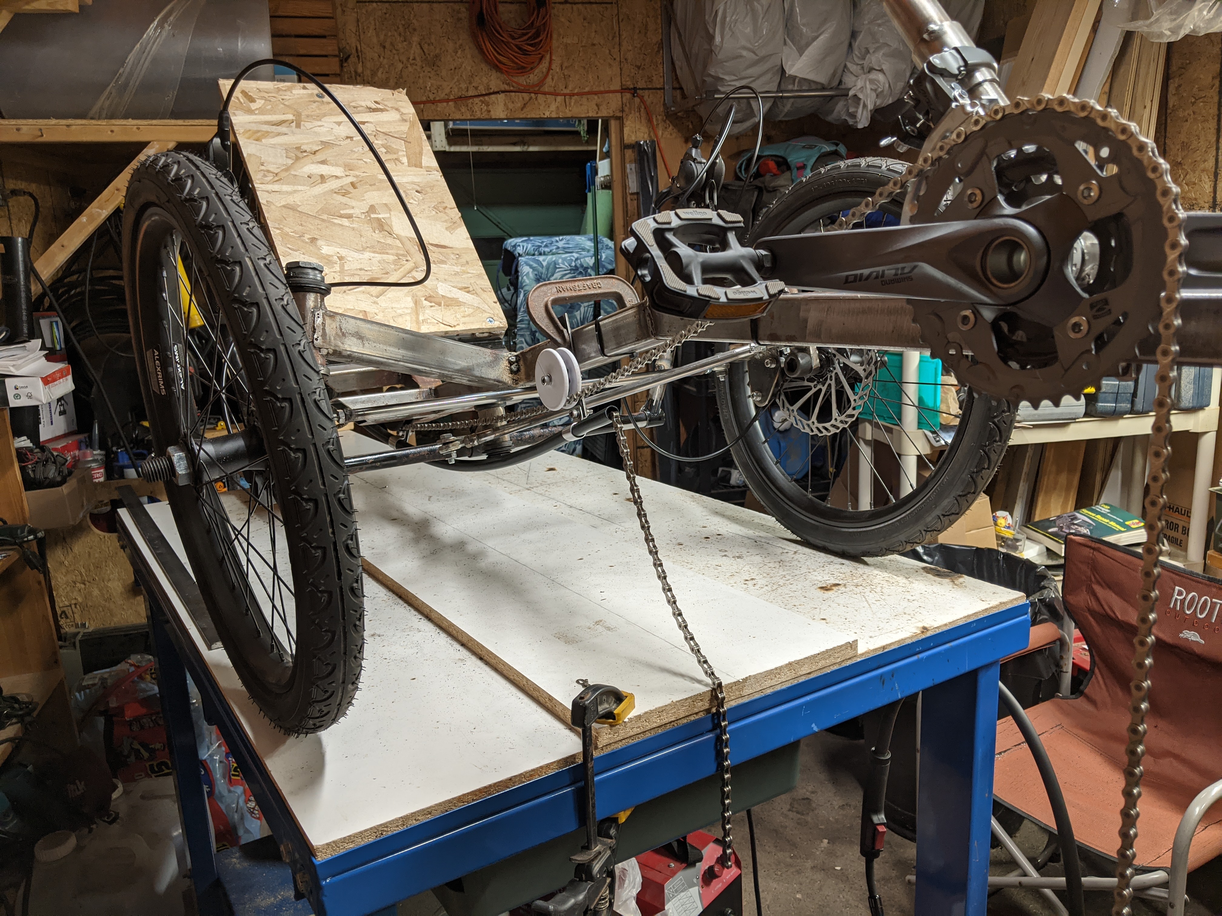
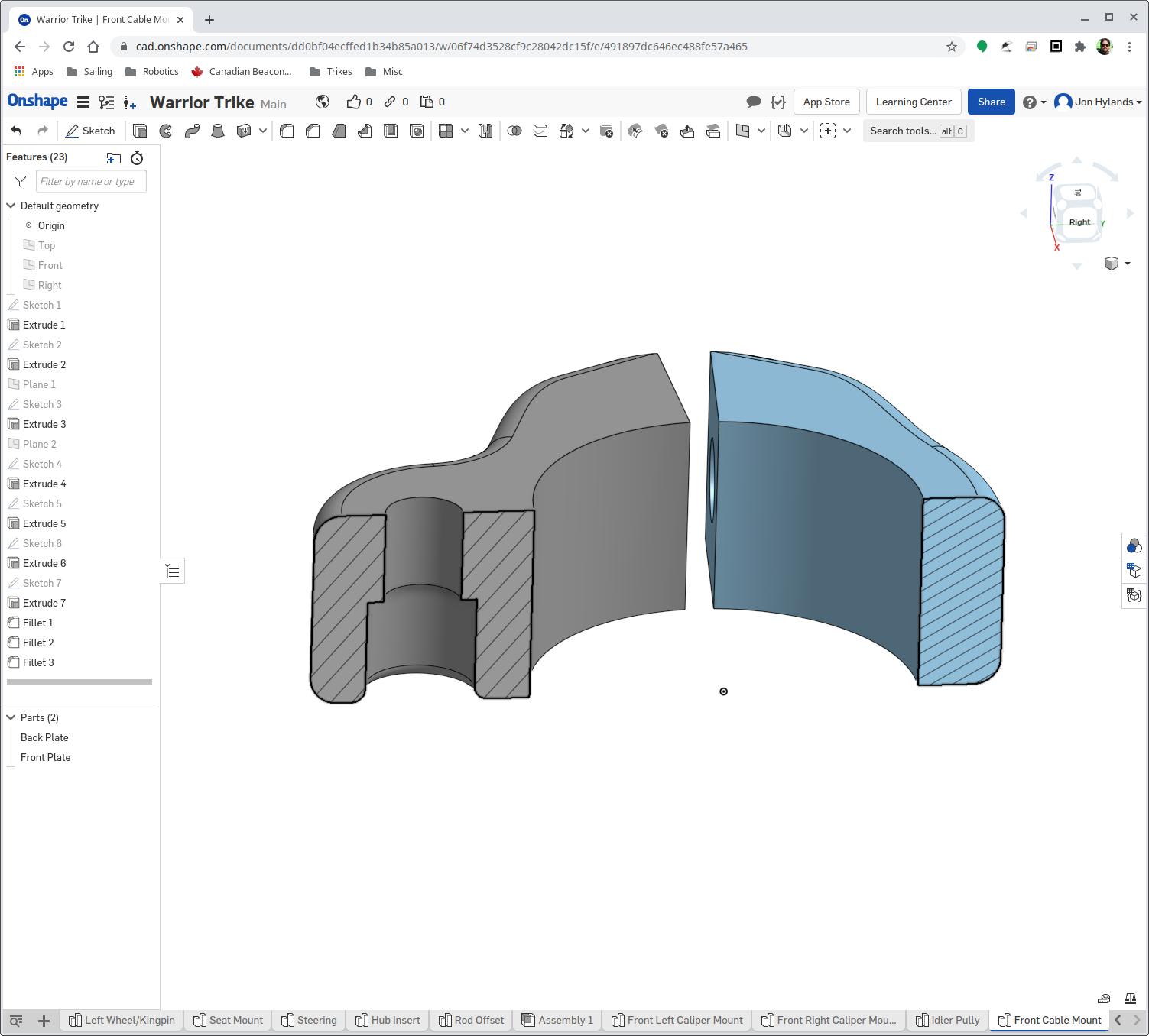
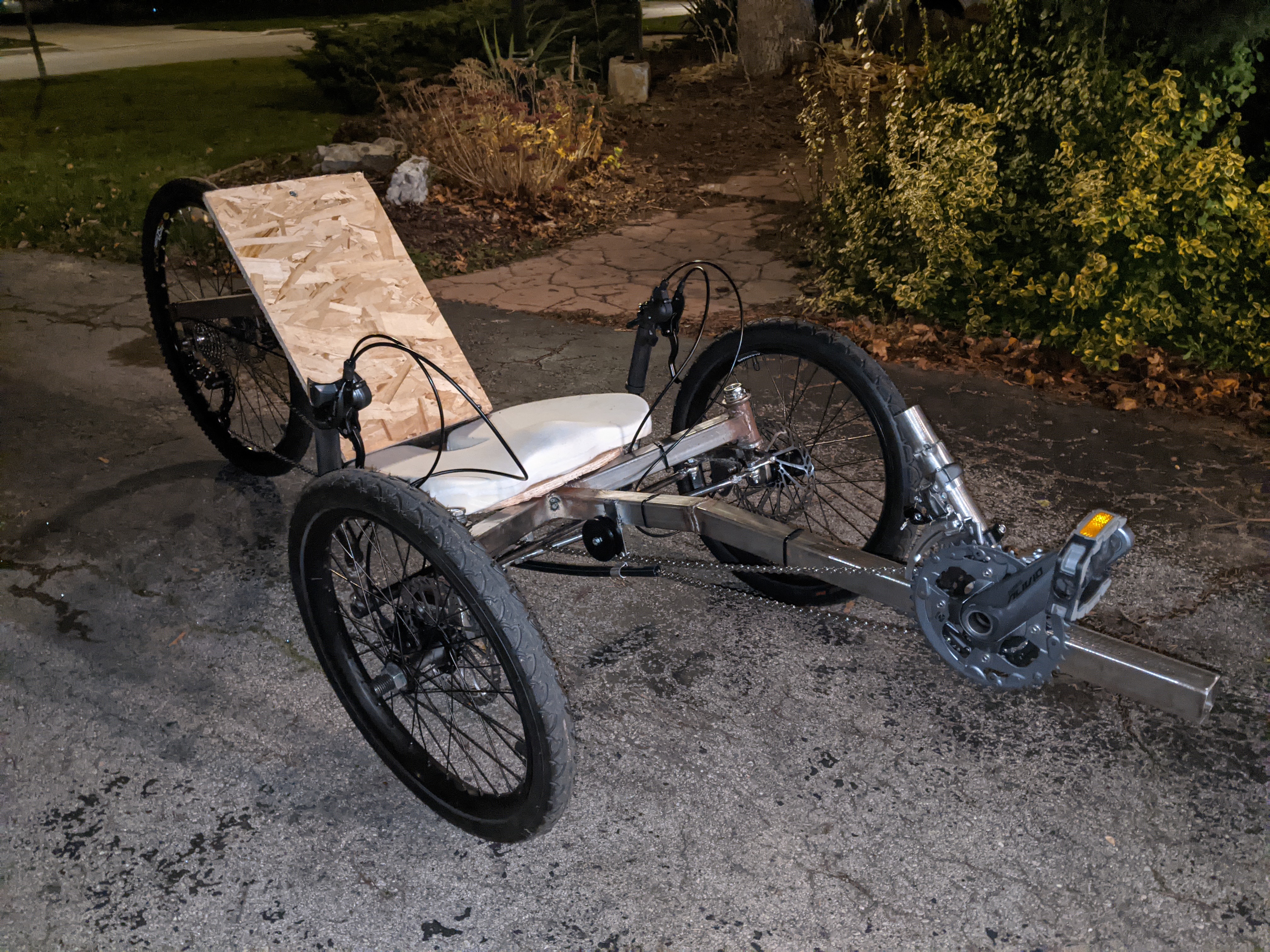
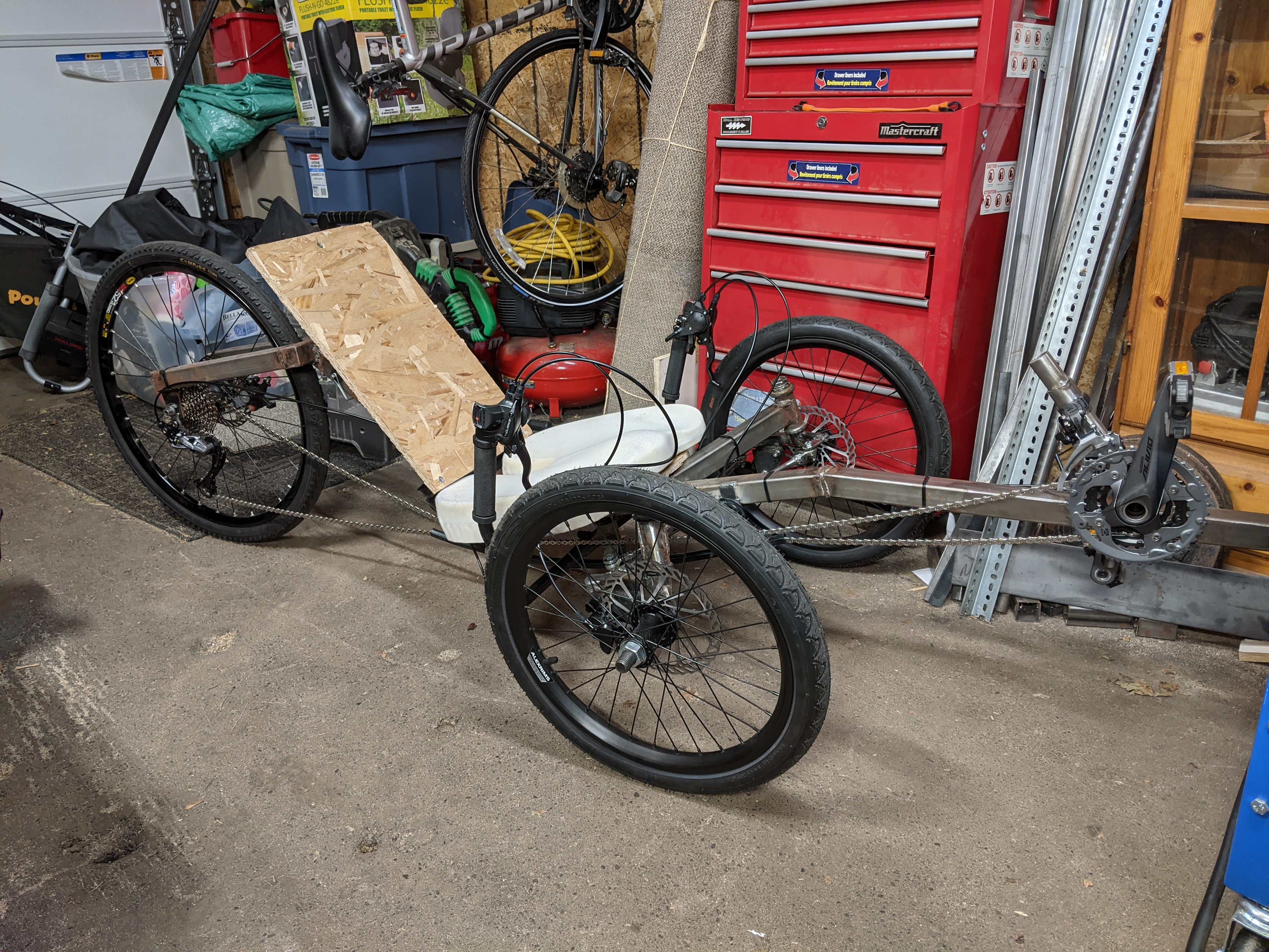
And so it begins - the drivetrain!

")
YouTube was having problems, so I think that you where trying to watch when they where offline.Youtube won't load that video for me. Will have another try tomorrow.
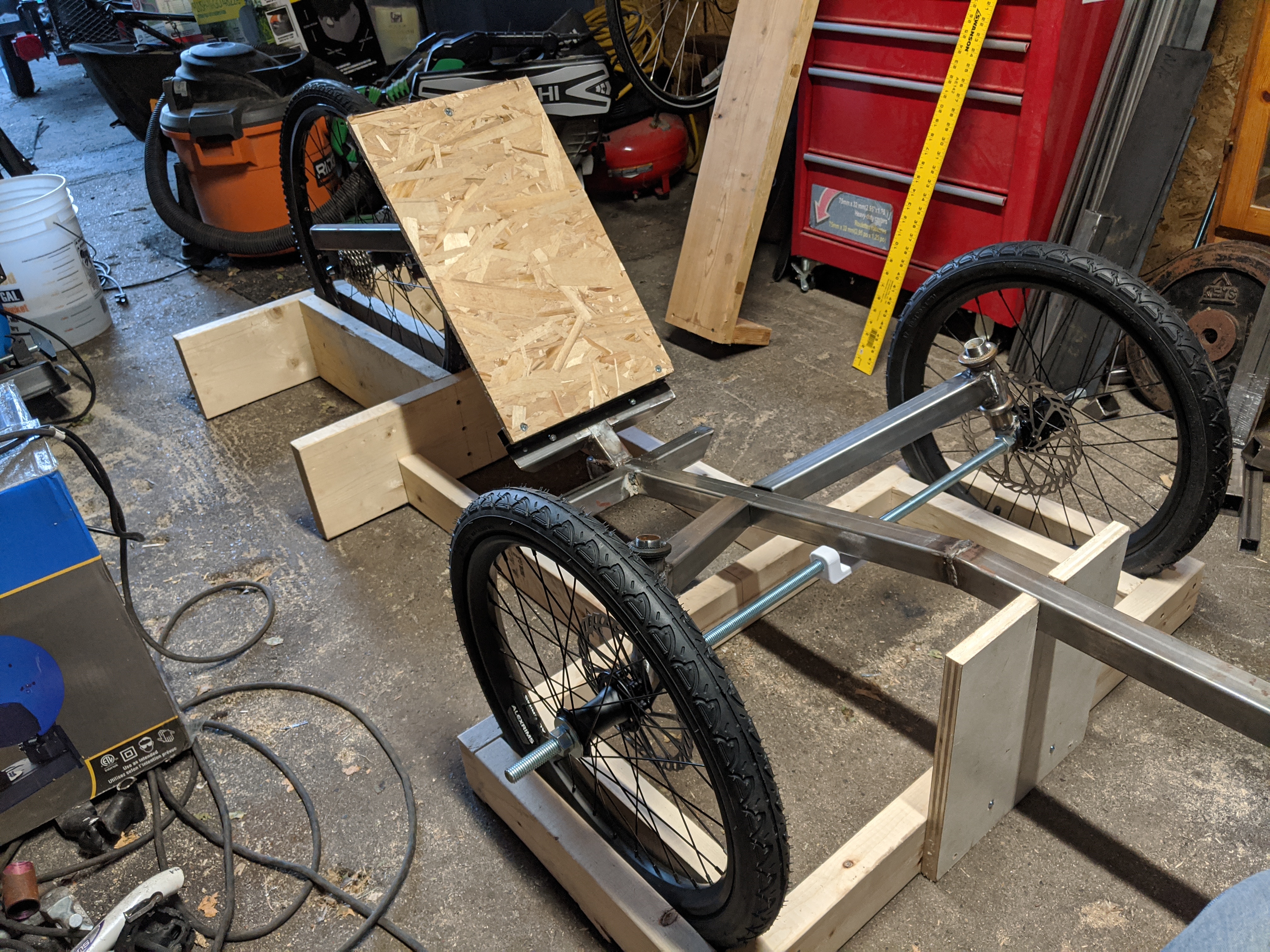
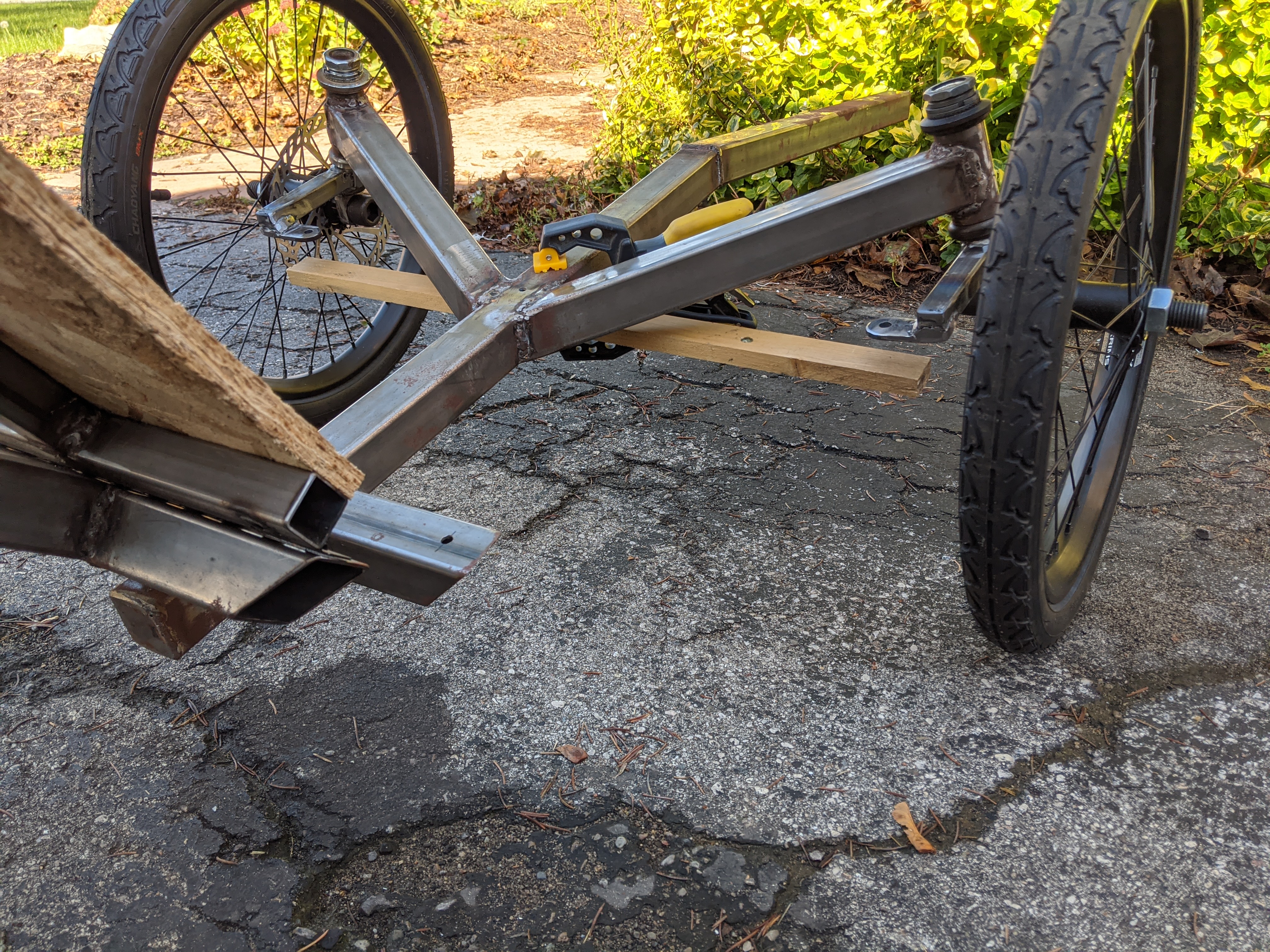
You could cut almost all the way through the wheel mount tab welds then adjust them with a hammer before re-welding. If you cut them on the inside leaving just enough on the outside to bend the cut will open slightly as you adjust them making it easier to weld them back up. You may need the wheels on and off a few times before you're happy.
I wish I had a £ for every time I've had to cut and adjust a weld!

