Jon's Warrior Build

That's actually not a bad idea. I have to chuck up the bolt in the lathe and take off a few thousandths near the head of the bolt - they get slightly larger there. I'll give it a shot, let you know what happens...
 
I'm working on a jig to hold the front tires in place while I figure out the cut and weld angles for the front arms. I already made one for the back tire a while back out of 2x10's, which you can see here:

IMG_20200817_124552.jpg


It holds the rear end tight and vertical, and holds the entire chassis in place.

I'm building something similar for the front, and this is just one I built from a scrap piece of 2x4 to test the fit on the front wheels:

IMG_20200817_124534.jpg


Now that I've determined that reality matches my measurements, I'm going to go buy a couple new pieces of 2x4 (the ones I have are all warped). The final jig will look something like this (from the top):

IMG_20200817_132046.jpg


The hatched portions are where the tires go. This ensures that all three wheels are pointing in the same direction and are aligned and vertical, which will hopefully make it simpler to cut and weld the parts together. I'll also include a bracket at the front that will hold the chassis tube at 11" off the ground (per the Warrior plans).
 
If you can find a long piece of studding, thread it through the two front hubs with big washers and nuts either side of each hub and kingpin sub assembly. It's a good way to keep the front wheels aligned whilst welding. M20 would obviously be best but it'll work with something smaller and more care.
 
Here's the jig for the front wheels:

IMG_20200817_202732.jpg


That puts the center of the tires 30" apart.

These are the two hub spacers I am 3D printing:

IMG_20200817_204000.jpg


They are about half done right now. They will slide right over the 5/8" threaded rod I bought tonight, and provide a 20mm outside diameter sleeve to fit inside the hubs and the axle tab.
 
Here's one of the spacers in the hub:

IMG_20200818_070045.jpg


And here's the setup, with a 3' long piece of 5/8" threaded stock:

IMG_20200818_071218.jpg


I don't think I'll be able to use it as is though - the chassis tube goes through the space occupied by the threaded rod...

Screenshot_2020-08-18_07-19-21.png


The center of the wheels is highlighted in orange. I'll have to look at maybe splitting the rod, and adding in a small diverter in the middle to loop under the chassis tube.
 
Here's the CAD model I whipped up, and just started printing. The holes are sized so I can tap them with a 5/8-11 tap (which I will have to pick up at Princess Auto, since I don't have one that size). I'll cut the threaded rod in half, and use this piece of plastic to get around the chassis tube.

Screenshot_2020-08-18_07-38-17.png
 
Onshape. I used it, but it was to limited for my use. But great free program for these things.

I didn't need to make that, but my arm is one straight tube in between the wheels.

Instead of the wheels, I would make it from wood. A hole in it and a short bold in it with the piece that you want to weld, on it and rest the frame on it. A bit more space to weld, because the wood is narrower than the wheel. Also easy to check if it is straight.
 
So after I 3D printed the piece, I decided I didn't want to spring for a 17/32 drill bit or a 5/8-11 tap which I'm not likely to ever use again, so I decided to re-print the part with the threads formed into the holes.

IMG_20200819_092231.jpg


That worked out pretty nicely, and the 5/8" threaded rod screws into it cleanly.

I cut the 36" long piece of rod in half, and then put it back together again:

IMG_20200819_120508.jpg


That works really well, and should give me the clearance I need for the chassis tube.
 
So, I finished one of the front axle mounts tonight:

IMG_20200819_173109.jpg


Its not perfect by any stretch, but it should be strong enough. A coat of paint and it will look quite nice, I think.

The second one is welded, but not finished. Enough that I could finally cut the steering booms:

IMG_20200819_201424.jpg


I'm really impressed - this thing is starting to look like a trike!

Here's another view:

IMG_20200819_201440.jpg


So its all held in place solidly, and more or less ready to weld the steering booms to the main chassis tube.

Popshot, thanks again for the "solid" axle idea - it made it much simpler to ensure that the tires are in fact vertical (and aligned) while all this is going on.
 
Just wait till you pained it. When I finished my frame i was happy with Joe it looked, but when the paint was on, it just changed a lot. Than it looks even better
 
I'm collecting parts to build a warrior and this thread has been very helpful, thank you for the post, quick question, I like the threaded rod axel to line up the wheels, is there some reason why you can't cut and use the threaded rod as the axel instead of a 20mm bolt?
 
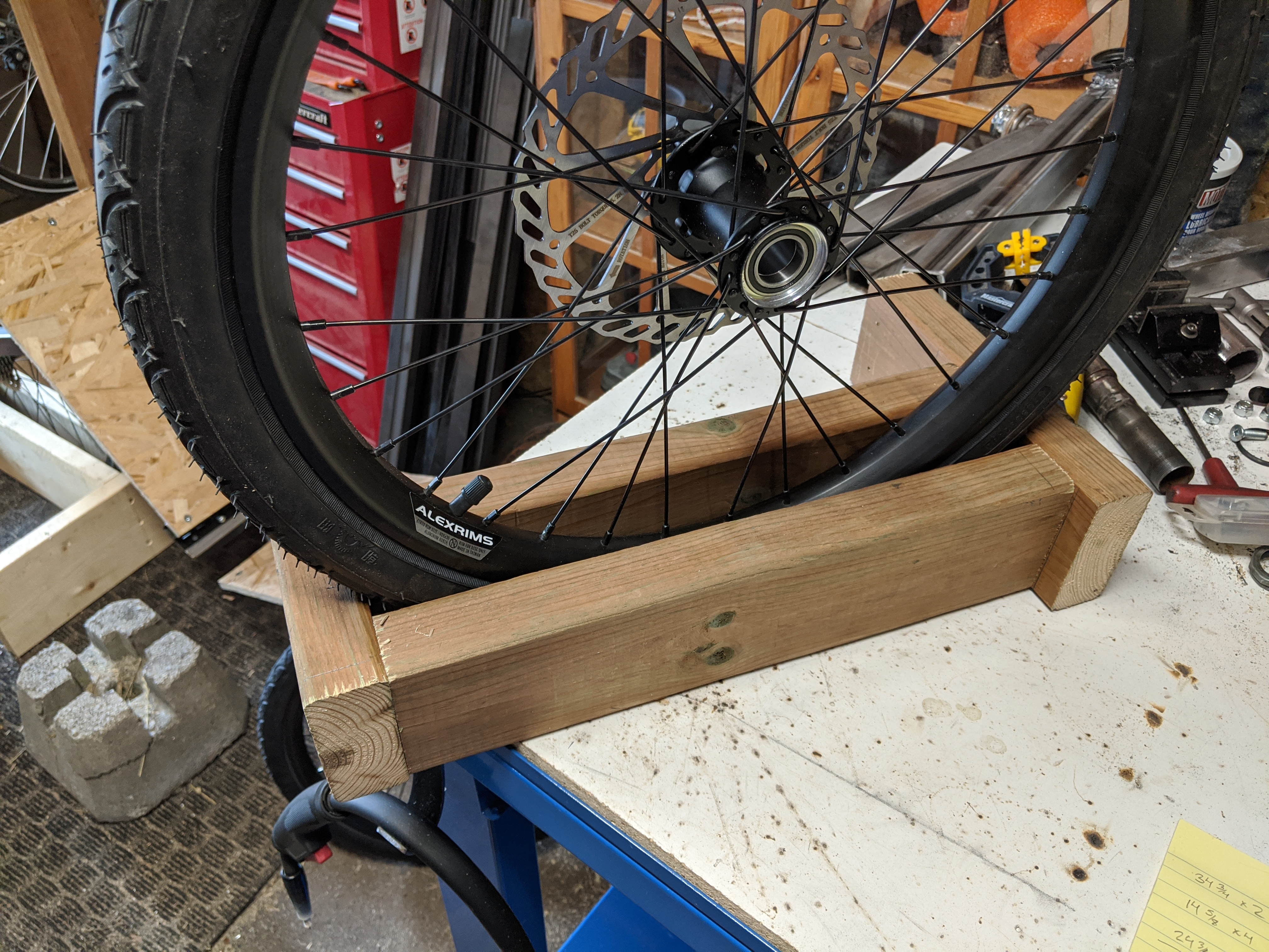
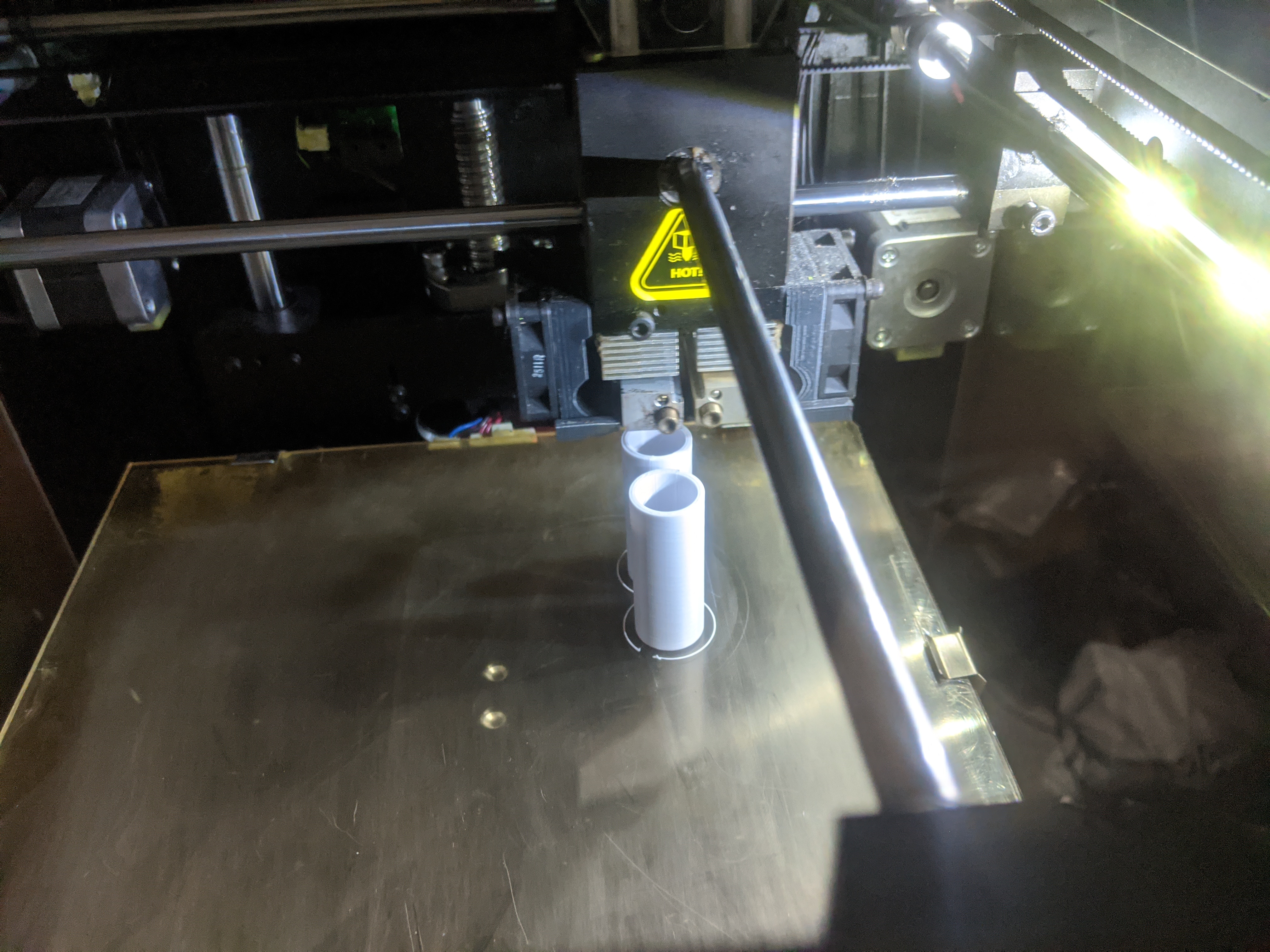
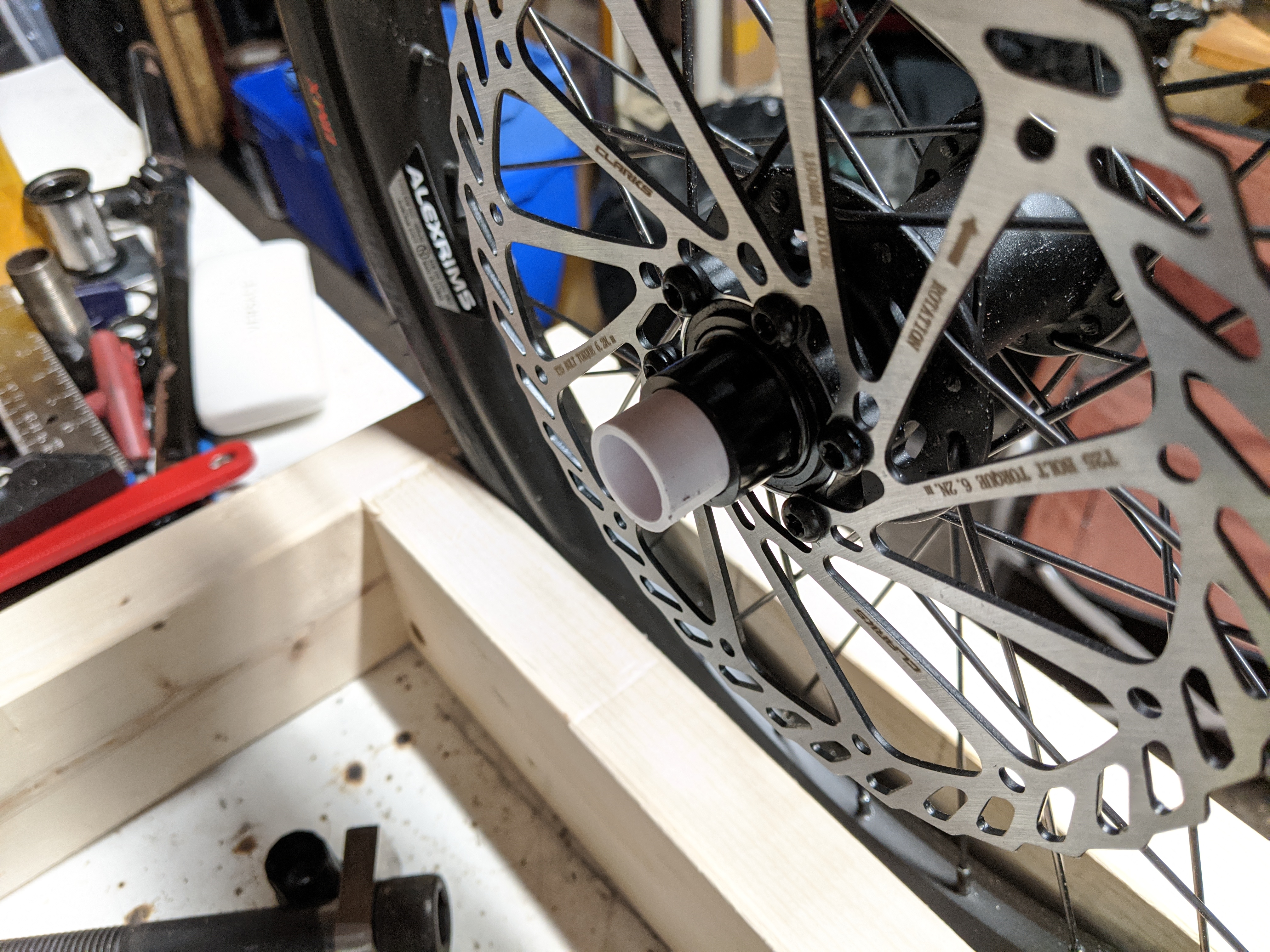
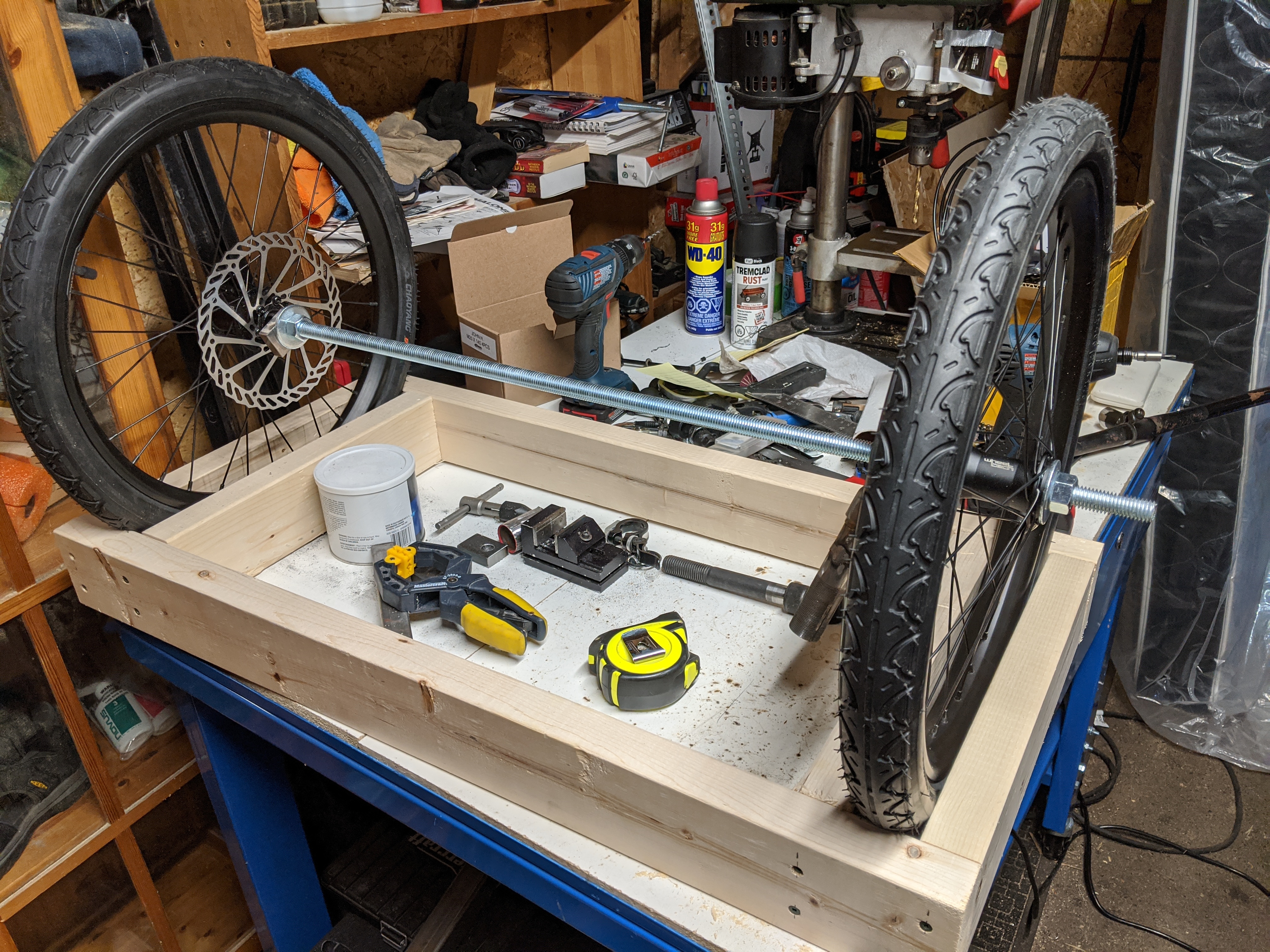
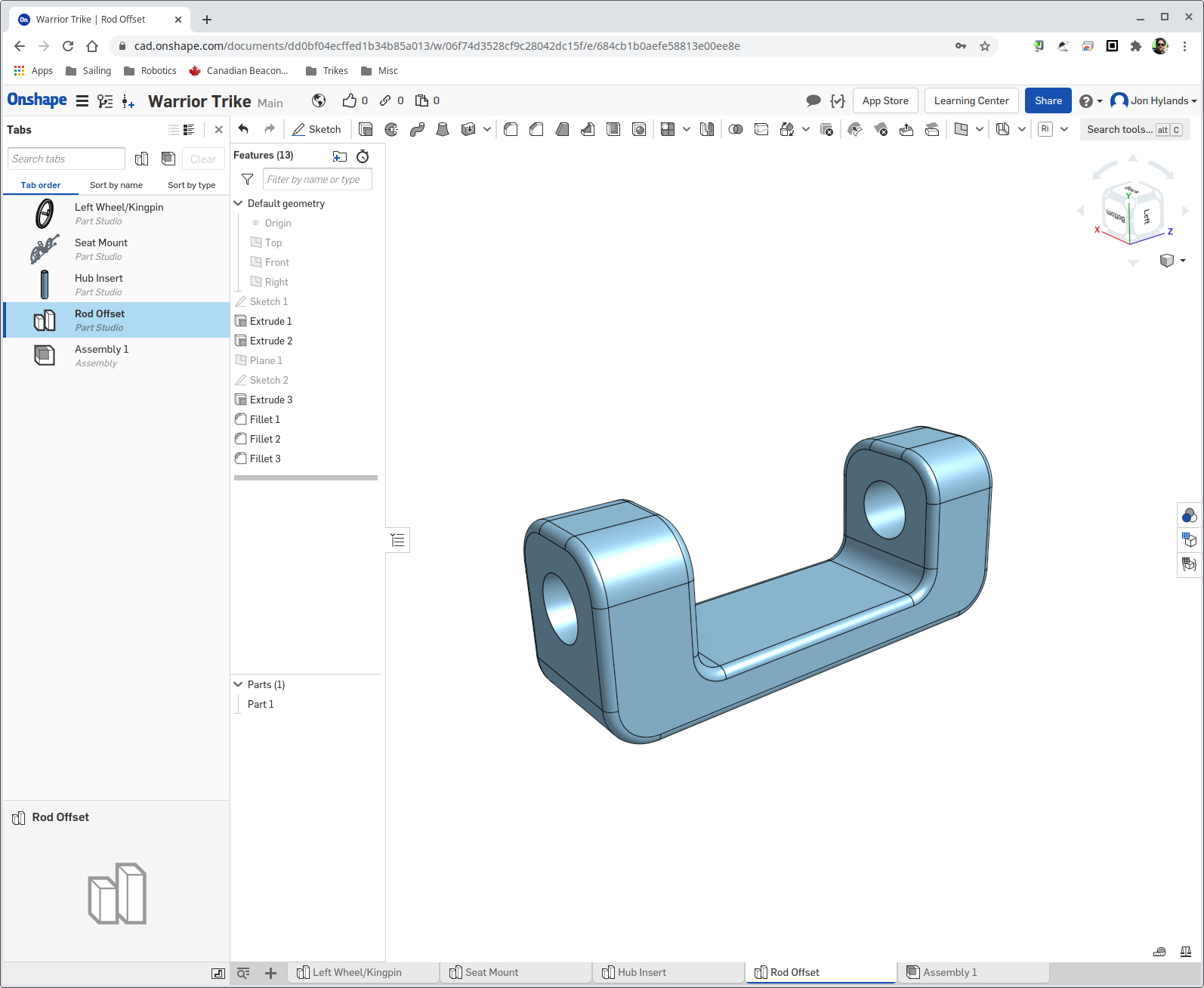
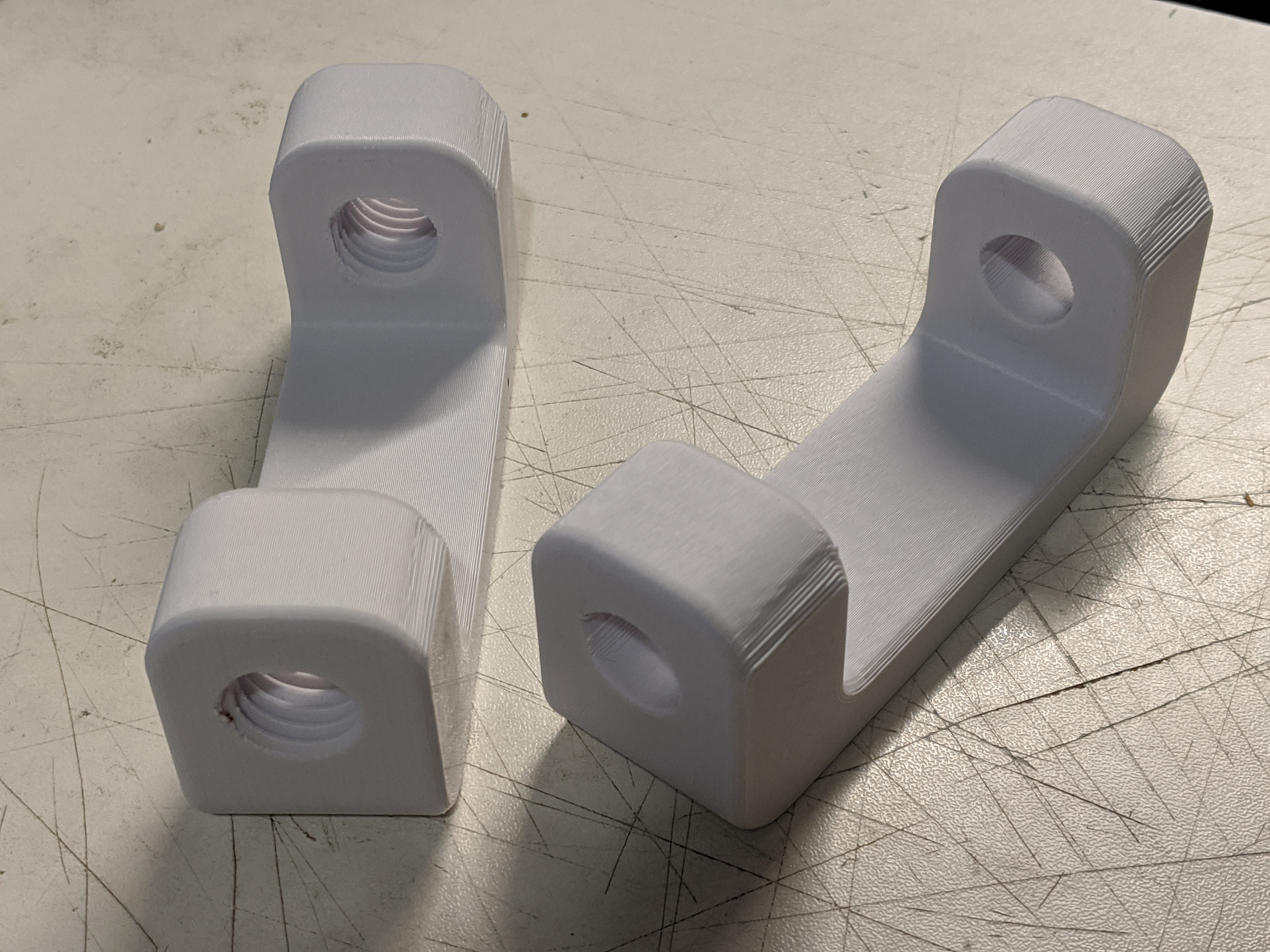
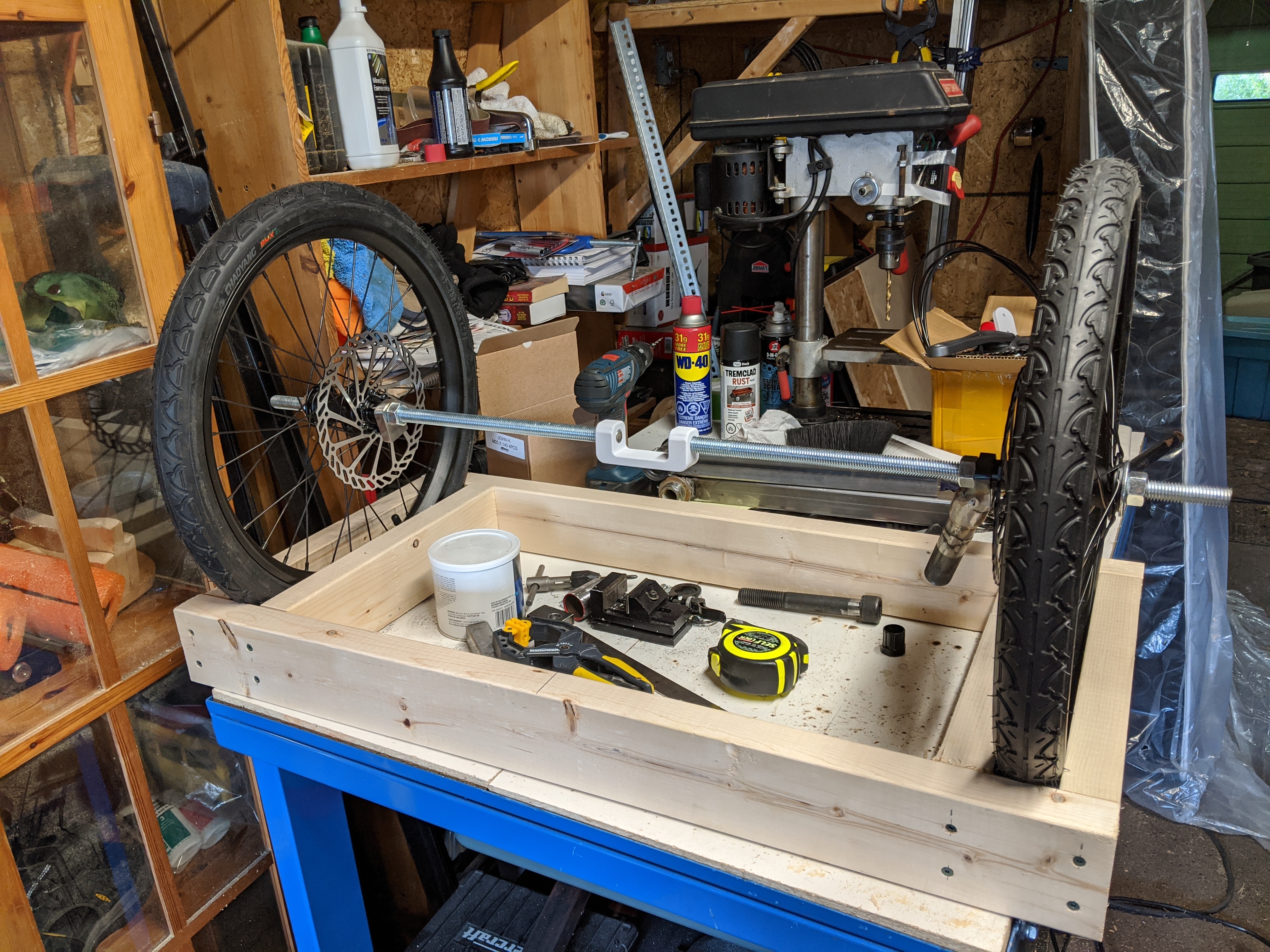
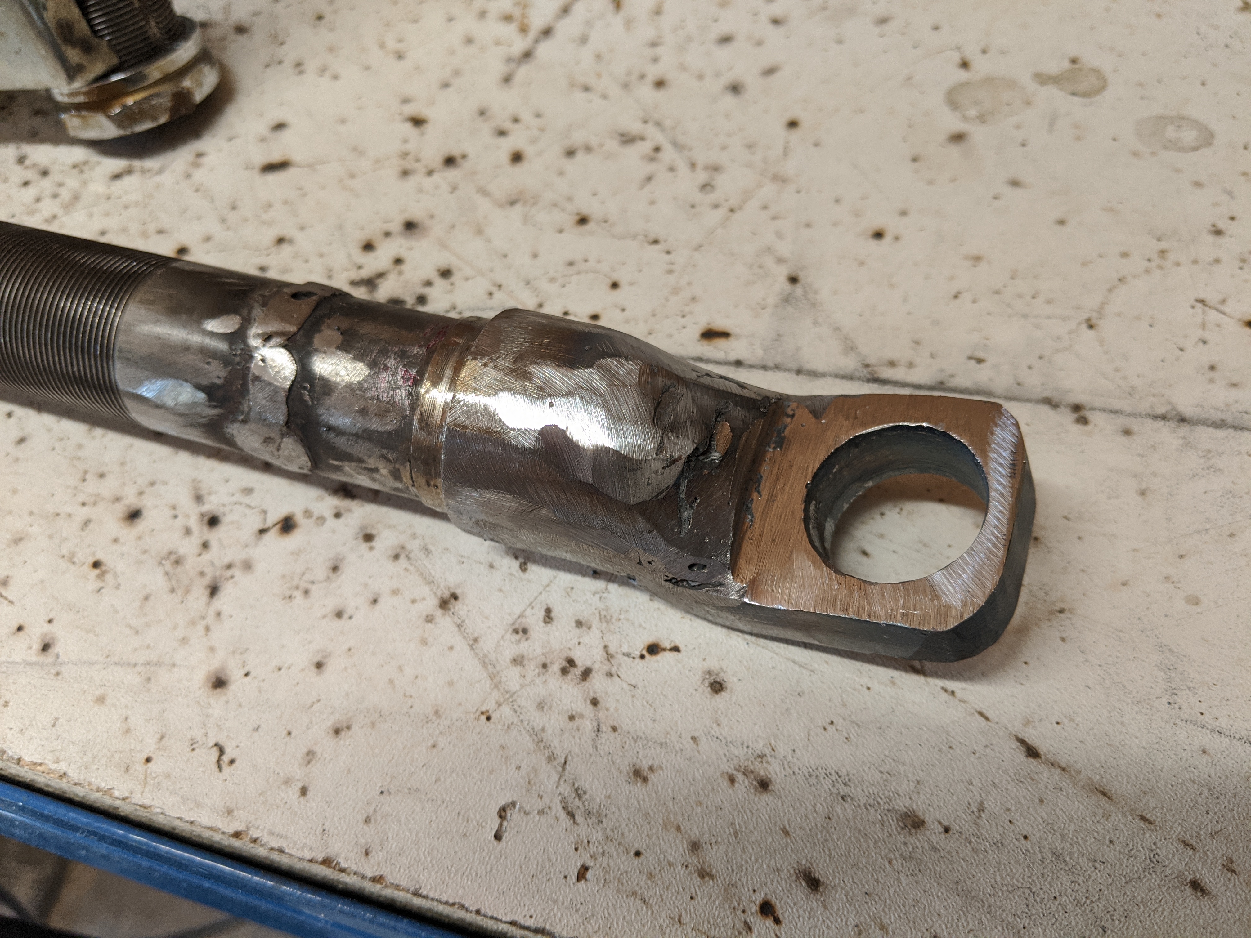
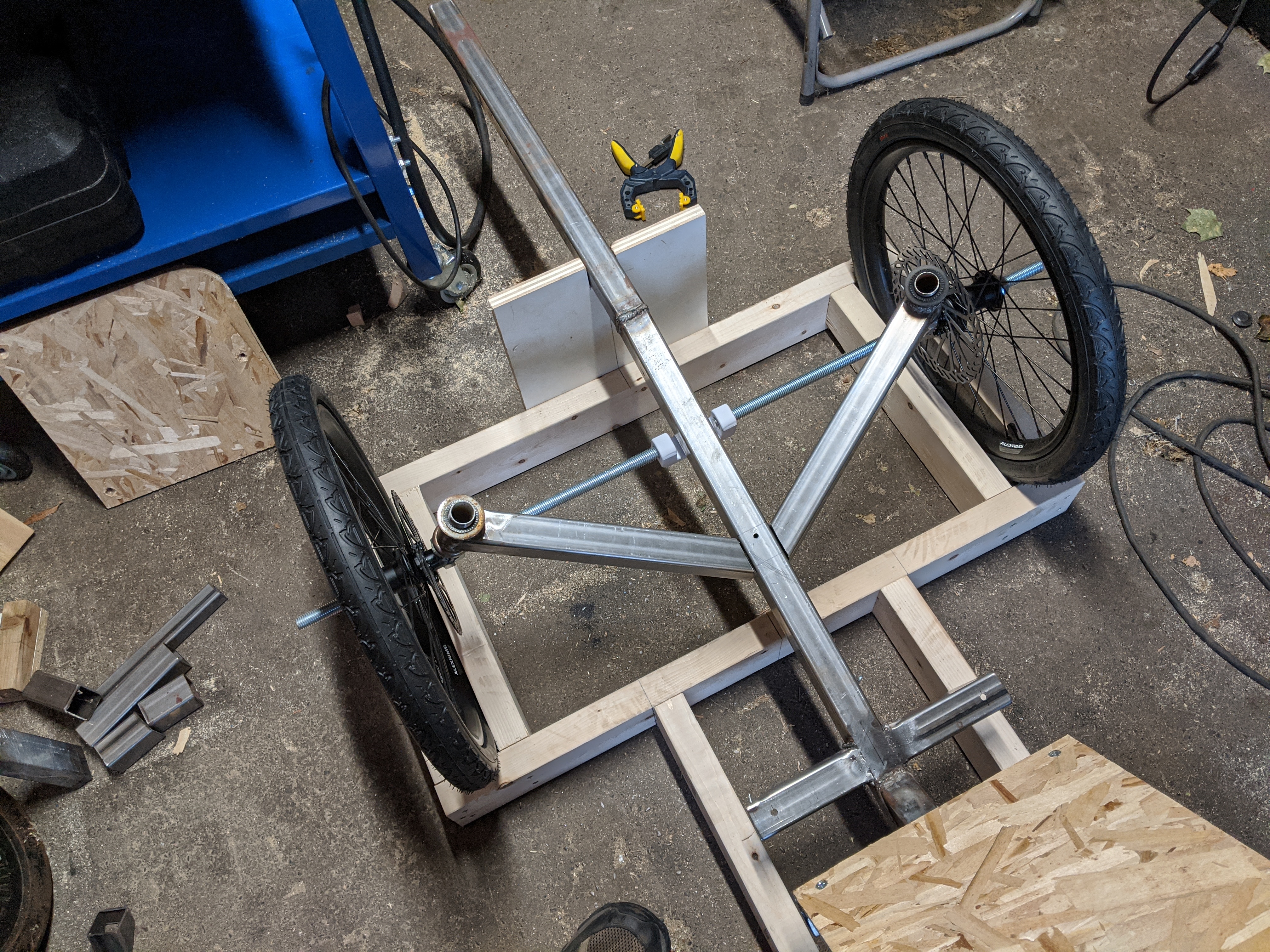
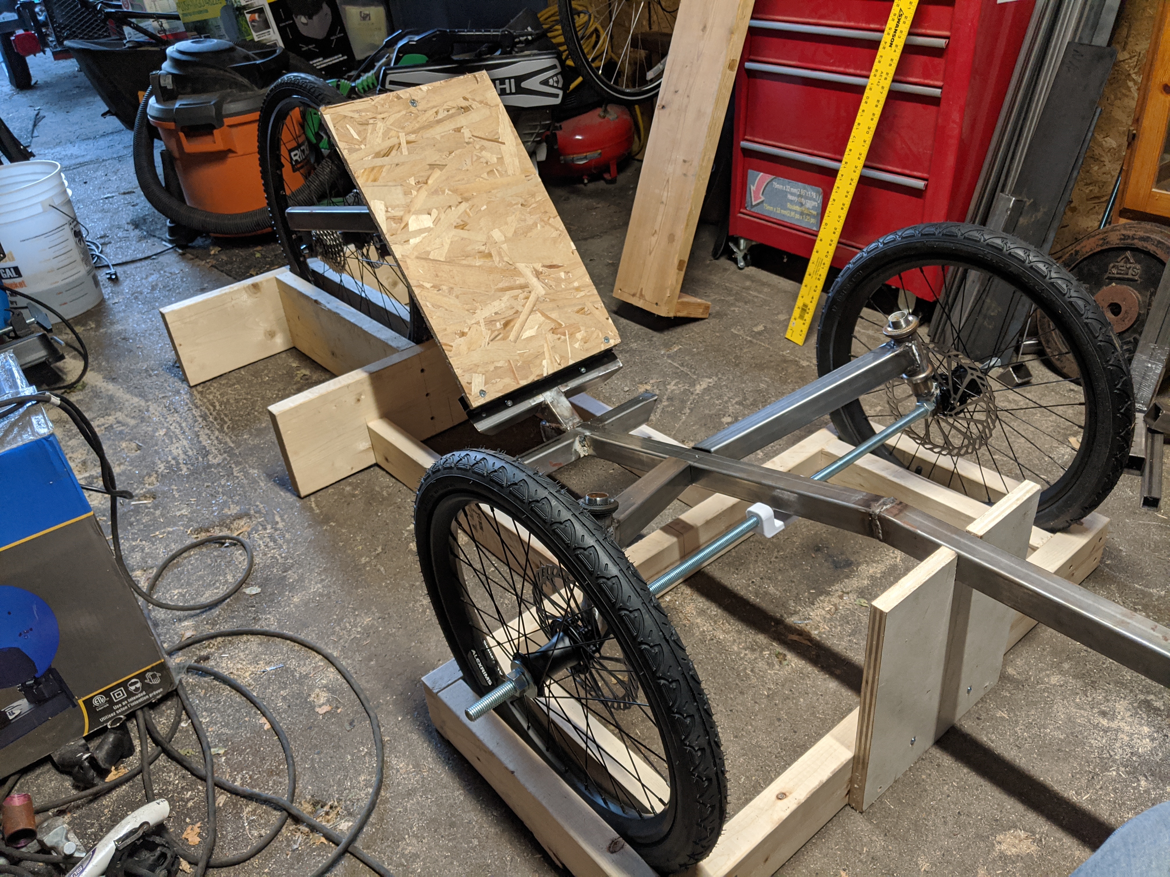
Yeah, the threaded rod is only 5/8" diameter, so its not the right size. I had to 3D print an insert for each side to make up the difference between 5/8" (about 15.9 mm) and 20mm. If you're going to bother getting 20mm through-hole wheel hubs, you should use the right size bolt. In any case, I'd be surprised if you could find threaded 20mm rod, especially for as cheap as the 5/8" rod was.

Also, its much better to use a bolt that is mostly smooth and not threaded over its length for this, so you get a better interface with the bearings inside the wheel.

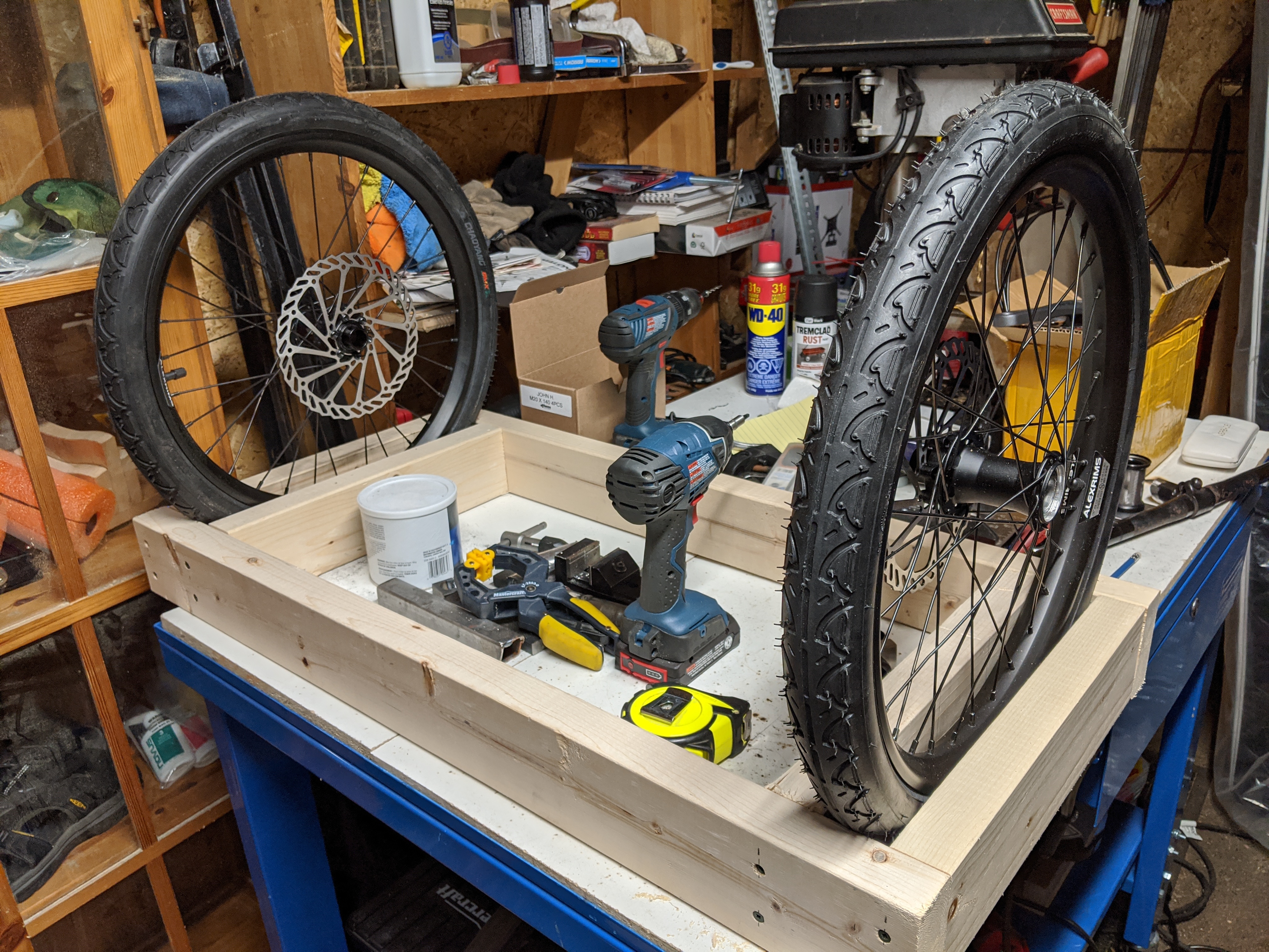
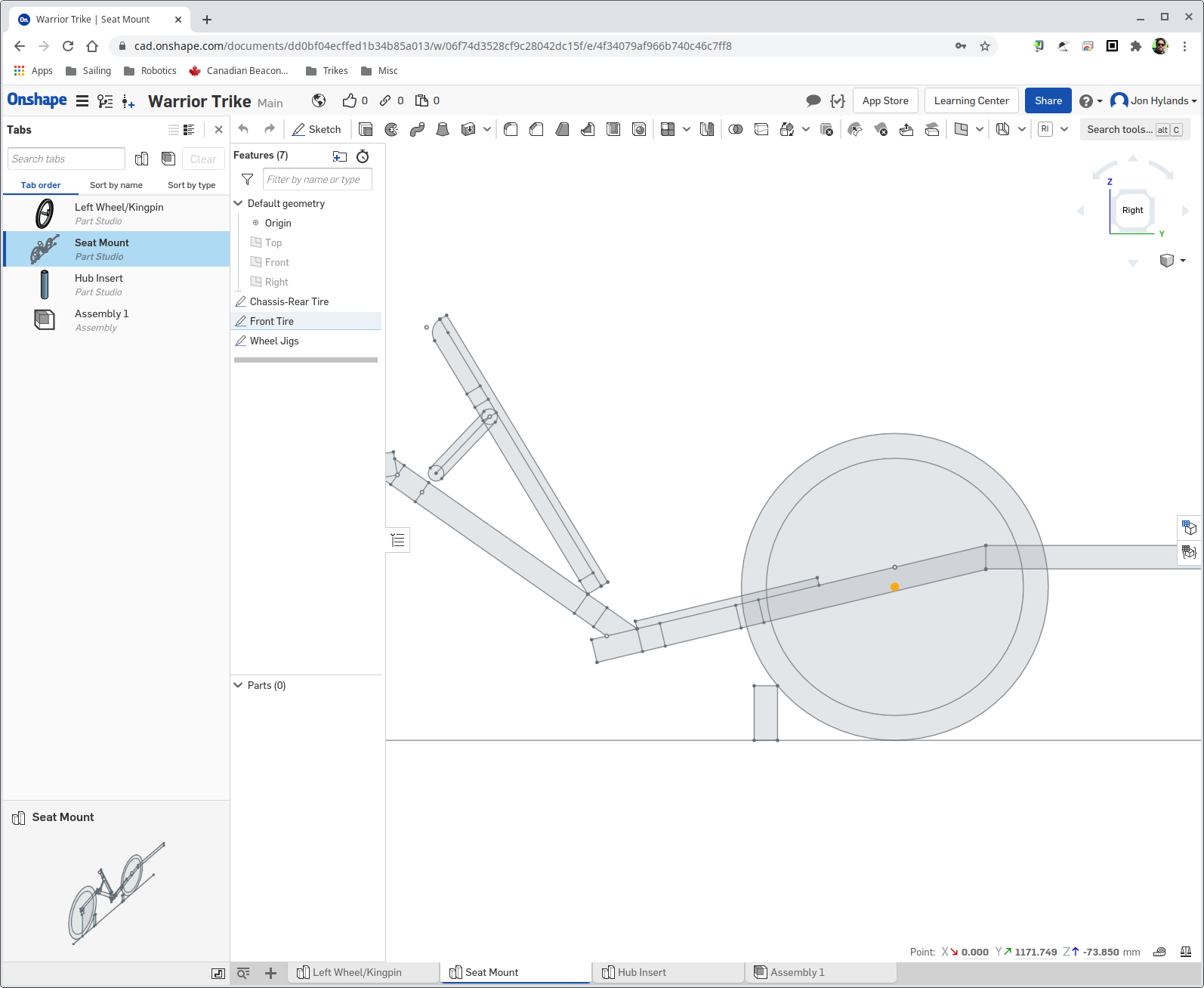
No, I haven't stopped working on the trike - we bought an RV trailer this summer, so most of my weekends have been spent away from home. I'll be getting back to this soon...
 
Thanks for the reply, that makes sense, so back on the list they go.

I'm glad to know you're still building I'm following along and it's been very helpful. I am just collecting stuff now and plan to start once winter sets in and the season is done.
 
I used m16 bolds with a 20x2 pipe over it. Works good.
In my next build I use m12 bolds but I will be able to use a threaded rod as a temporary repair.
 
Back
Top