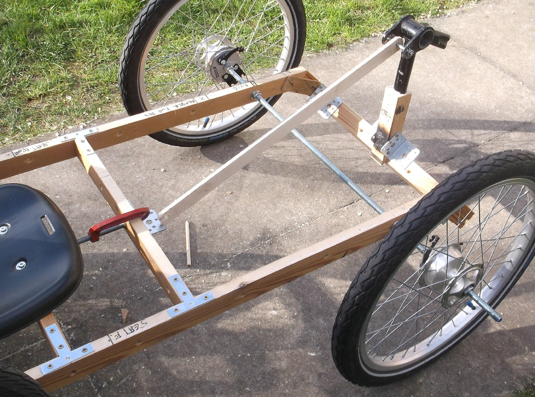
Yes and I have some , just used what was at hand at the moment...If you use female rod-ends and M12 studding and nuts, can you not get increased angles?")
Paul

Yes and I have some , just used what was at hand at the moment...If you use female rod-ends and M12 studding and nuts, can you not get increased angles?
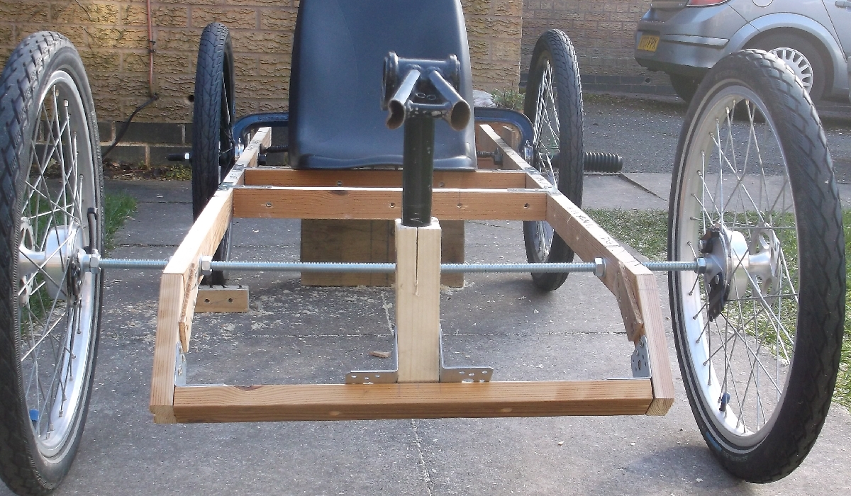
+ MaddoxI've bent male M10 rod ends in similar positions. They bent alarmingly easily too. I always try to work things to have female rod ends where I can. For the probable upcoming 4ws quad I've located some extra strong M12 units as I had to use male ones.

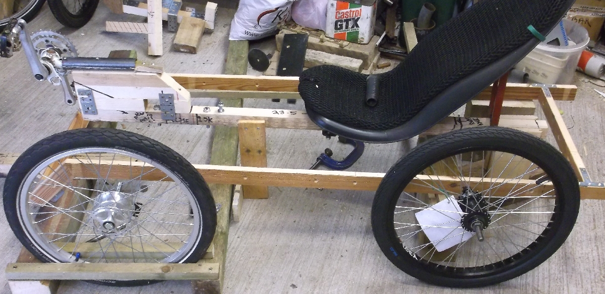
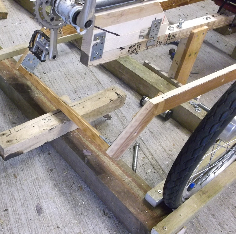
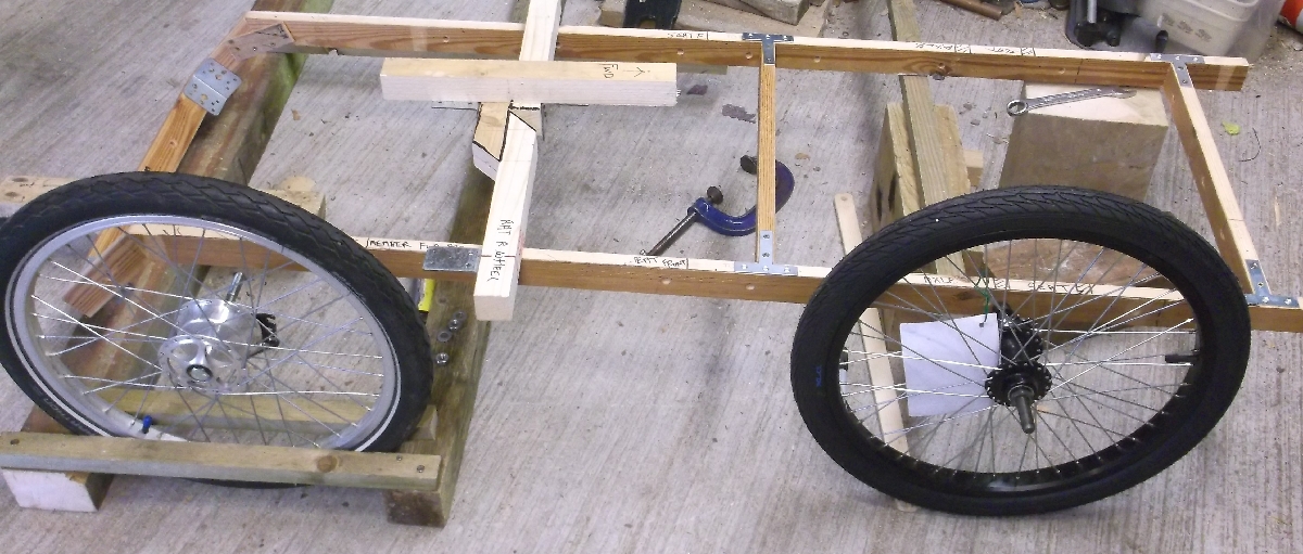

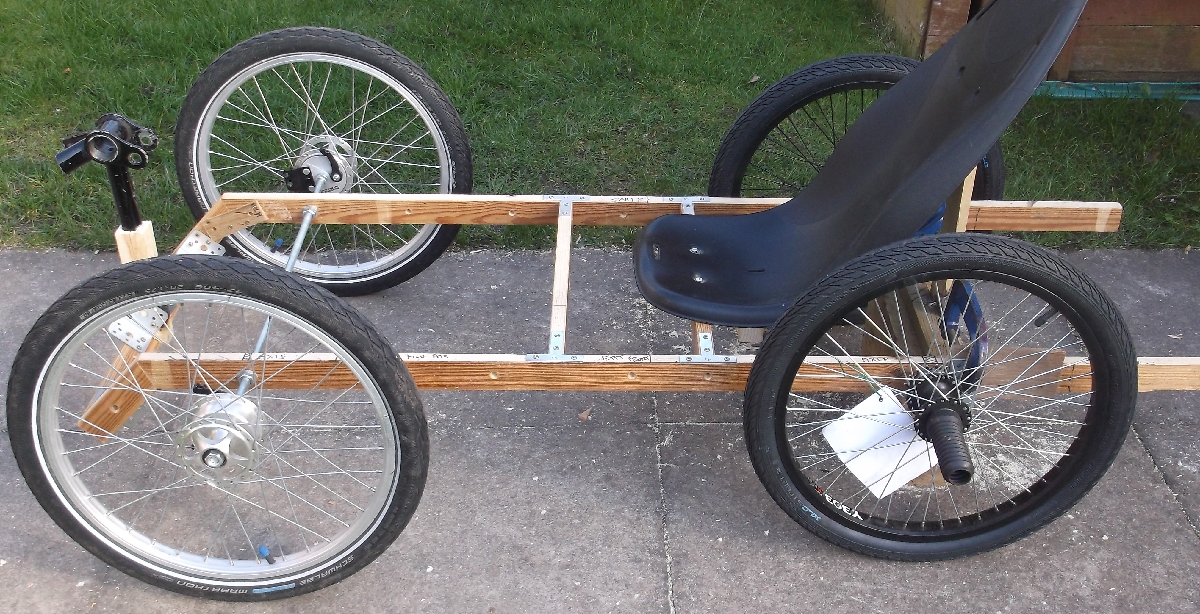

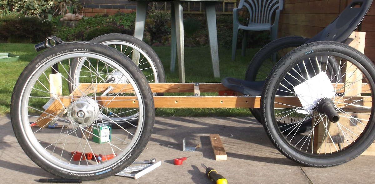
One of the drawbacks with the twin spar perimeter frame is each wheel is now free to act on the rail it is attached to to try to twist it. With a single spar that twisting force is stopped by the other wheel mounted to the other side of the central rail. It's all but impossible to brace as your feet need that space. The further towards the axle you can get that front crossmember the more it will help resist that force.
That is a ' I hope so situation 'Do you have enough room between the wheel and those rails for the wheel to turn enough? It doesn't look enough but could be camera angle trickery.

But you would not have had as much fun, and this may prove to be very interesting to many people.I started this thread 19th December , if I had stuck to plan A a delta it would probably have been built by now ?
It would also have been less effort to use a basic CAD program.